The story behind the birth of the modern motorcycle linkage
To understand where the modern motorcycle linkage came from, its useful to go back to the original engineering rather than working backwards from today’s systems.
In 1974, Donald G. Richardson developed a rear suspension system for a motocross motorcycle.
On 25 November 1974 he filed US Patent Application 526,971. On 23 September 1975 it became US Patent 3,907,332 Suspension System.
Richardson had been working around race cars and encountered a car using a rocker/linkage suspension. He initially thought the linkage was rather pointless. But he noticed something important: the linkage could convert the relatively linear movement of the wheel into a non-linear movement of the shock.
In his words, he realised that, “depending on the linkage geometry, you could create a non-linear wheel rate”.
In the patent Richardson explains what the mechanism is intended to do.
The problem
The patent starts by putting the problem into context.
“Motorcycles intended for rough terrain need suspension at both ends, but the rear suspension has a particularly difficult job. It has to allow the wheel to move through relatively small disturbances without making the motorcycle harsh, while still having enough resistance available for much larger movements.”
The patent refers to previous variable rate suspension work and states:
“The purpose of the variable spring rate is to provide increased loading and greater deflection and prevent bottoming out.”
Richardson wasn’t claiming that he had invented the concept of a variable rate, he was applying the principle to a motorcycle.
The patent specifically acknowledges earlier variable rate suspension systems and also notes that rising-rate systems had already been used in racing cars. The problem was that the geometry and packaging of those four-wheel systems did not simply transfer to a two-wheel motorcycle.
Figure 1: The motorcycle
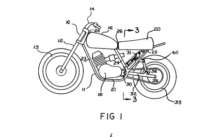
Richardson’s first patent drawing shows the complete motorcycle using a conventional swingarm. Instead of using twin shocks directly between the swingarm and frame, a single shock is incorporated into a linkage system located within the frame.
This was important for packaging. The patent’s abstract specifically identifies two characteristics: “the spring is located within the frame and does not add to the width of the vehicle” and: “the linkage is so connected that the force of the spring increases with increasing deflection of the rear wheel.”
It wasn’t simply a method of mounting a shock, the linkage was being used to transform the spring rate at the wheel.
Figure 2: The mechanism
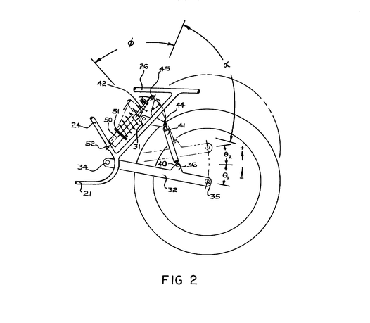
Figure 2. shows the suspension mechanism.
The swingarm is connected to a linkage and bell crank.
The shock is mounted between the frame and the linkage.
As the swingarm moves, the linkage rotates the bell crank.
The spring therefore doesn’t compress in a simple one-to-one relationship with the rear wheel. Instead, the mechanical advantage changes as the suspension moves.
That changing mechanical advantage is what produces the rising rate.
This is the important point: The spring itself is not necessarily progressive; the resultant action is.
As Richardson says: “The rising rate is accomplished using a uniform rate spring similar to that producing the straight-line characteristic. The rising rate is obtained because of the linkage.”
A linear spring can therefore produce a non-linear wheel rate when combined with suitable linkage geometry.
Figure 4: Three positions of the suspension
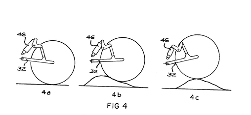
Figure 4. shows the linkage in three different states of deflection.
At minimum deflection, the linkage has one mechanical relationship.
As the wheel moves further, the bell crank rotates.
At full deflection, the geometry has changed considerably.
As the wheel rises over the bump the relationship between rear-wheel movement and spring compression is continually changing. It can be expressed in simple engineering terms as: Wheel force = spring force × effective linkage ratio
As the linkage ratio changes, the incremental wheel force required to produce another millimetre of movement changes.
Whilst the spring may be linear, the wheel rate isn’t.
The patent shows how to alter the progression
Richardson didn’t simply claim that his linkage was progressive. He explained how the progression could be changed.
The patent states: “This rising rate characteristic may be varied by changing the position of points 44 and 45…” and explains that this could be achieved through different mounting positions.
In other words: change the linkage geometry – change the motion ratio – change the wheel-rate curve. The exact same thing that linkage designers do today.
Figure 5: The curve
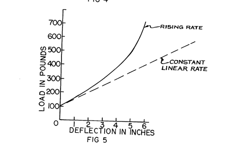
In figure 5. Richardson plots force against wheel deflection.
Two curves are shown:
- Constant / linear rate
- rising rate
The rising-rate curve begins relatively gently and becomes progressively steeper as wheel deflection increases, the same as we would see from a modern rising-rate linkage.
Early in the stroke: relatively little force for a given wheel movement.
Deeper in the stroke: increasing force for each additional millimetre.
Near the end: substantially greater resistance to further movement.
This gives the suspension a useful compromise.
You don’t have to choose between an extremely soft suspension that uses all its travel easily and an extremely stiff suspension that resists large impacts from the beginning of the stroke. The linkage allows the two characteristics to coexist.
Bottoming out
There are arguments that linkages were introduced for other reasons, but the original sources are unambiguous: preventing bottoming was one of the core motivations. Richardson’s patent explicitly lists increased loading, greater deflection, and avoiding bottoming as reasons for using a variable‑rate system. The Federal Circuit later summarised his invention in the same terms:
“An optimum rear‑wheel suspension will maintain tire contact with the ground despite deflection by irregularities, will avoid ‘bottoming out’ … yet will achieve a smooth ride without reduction in safety.”
Whatever theories have been attached to linkage designs over the last half‑century, the documents surrounding the invention make Richardson’s intent very clear.
Testing
The patent and court record don’t just describe the theory; they also document how the system behaved in practice.
In mid-1974 Richardson replaced the conventional twin shock arrangement on his own bike with a single shock and a linkage consisting of a bell crank and connecting rod.
The court records that the linkage generated a “rising rate” and produced a far superior ride while eliminating dangerous bottoming.
Richardson described his first ride over a hilly construction site as: “utopia.”
He described the behaviour over hard bumps as: “uncanny because it was so smooth” and said: “The rear end didn’t kick up. It just didn’t bottom out and stayed down.”
From invention to Suzuki
In October 1978 Richardson entered into an agreement with Suzuki giving the company an exclusive option to test and evaluate his suspension and potentially license the patent and associated technical information. Richardson worked directly with Suzuki on development. In early 1979 he and his colleague Cazort developed an improvement they called the Alternate Shock Mount.
In May 1979 Richardson’s first prototype for Suzuki was installed in a 1978 Suzuki production motorcycle and tested in Japan.
The court record describes the response from Suzuki’s test riders. They reportedly said they could: “see the bumps but not feel them.”
Following the tests, the court recorded that Suzuki decided to put the linkage-generated rising-rate suspension into production and began development work for that purpose.
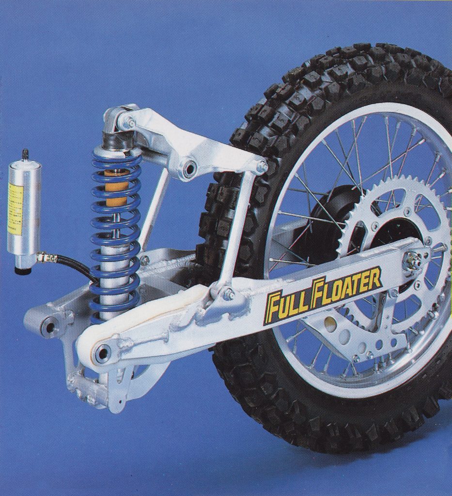
That development ultimately became Suzuki’s Full Floater suspension.
The patent dispute
The relationship between Richardson and Suzuki subsequently broke down.
Suzuki filed its own patent application covering the Alternate Shock Mount arrangement and another modification.
Richardson eventually brought legal action.
The resulting litigation lasted years and involved patent infringement, contractual issues, trade secrets and related claims.
Richardson eventually sued Suzuki, claiming that the system infringed his patent and that Suzuki had misappropriated trade secrets.
The dispute became a major patent case. In 1987, a federal jury found in Richardson’s favour on patent infringement and certain trade-secret claims. Contemporary reporting described the potential award as ranging from approximately $6 million to $19 million depending on the number of motorcycles involved.
The lesson from the original drawings
Almost fifty years later, that basic principle remains at the heart of the rear suspension on most motorcycles.
The Richardson patent is interesting because it shows how the fundamental idea behind motorcycle linkage suspension can be understood without the benefit of 50 years of hindsight.
The basic problem was straightforward:
A motorcycle needs suspension that can move freely over relatively small disturbances but needs substantially greater resistance as the available travel is consumed.
References
Donald G. Richardson — US 3,907,332, “Suspension System”, filed 25 November 1974, granted 23 September 1975. The original patent includes the five engineering drawings, the rising-rate force/deflection graph and Richardson’s explanation of how changing linkage geometry alters the rate.
Richardson v. Suzuki Motor Co., Ltd., 868 F.2d 1226 (Fed. Cir. 1989). The subsequent court decision provides unusually detailed historical and technical evidence about Richardson’s prototype, the development work with Suzuki, the rising-rate mechanism and the subsequent dispute.
Los Angeles Times, 28 March 1987. reporting of the original jury verdict and Richardson/Suzuki dispute.
Los Angeles Times, 4 June 1987. reporting on the district court’s treatment of the jury award and trade-secret findings.